Smart Temperature-Controlled Desk Fan
AVR-based embedded control system using temperature sensing, PWM fan control, servo movement, user input, and multi-mode system logic.
Project Overview
The Smart Temperature-Controlled Desk Fan is an embedded systems project built around an Arduino-compatible Elegoo Uno R3 using the ATmega328P microcontroller. The system reads temperature data, processes user input, and controls multiple outputs including fan speed, servo movement, and buzzer feedback.
The project was originally developed as an Arduino-style embedded system and later rebuilt in AVR C using Microchip Studio. This made the project stronger technically because the system behavior was implemented closer to the microcontroller level instead of relying only on simplified Arduino functions.
The final system demonstrates practical embedded control by combining sensor input, PWM output, ADC input, button logic, and actuator behavior into one complete smart fan platform.
Project Specs
This project included embedded C programming, hardware pin mapping, schematic planning, sensor integration, PWM fan control, analog input handling, servo output, button-based mode switching, buzzer feedback, and system testing.
Engineering Challenges
One of the main challenges was coordinating several inputs and outputs at the same time without turning the project into separate disconnected features. The system needed to read temperature data, respond to a mode button, process potentiometer input, control fan speed, move a servo, and trigger buzzer feedback in a structured way.
Another challenge was rebuilding the behavior in AVR C. This required more direct control over the ATmega328P’s embedded features and forced the system logic to be organized around registers, timing, pin behavior, and hardware-level control.
- Reading temperature input from the DHT11 sensor
- Controlling fan speed with PWM output
- Using ADC input from a potentiometer for manual control
- Managing servo movement alongside fan behavior
- Handling button-based mode switching
- Providing buzzer feedback for system events
- Keeping all components organized in one reliable embedded system
System Design
The Smart Fan uses the ATmega328P as the main embedded controller. A DHT11 temperature sensor provides environmental input, while a potentiometer gives the user manual control through analog input. A button is used to switch operating modes, allowing the fan to respond differently depending on the selected behavior.
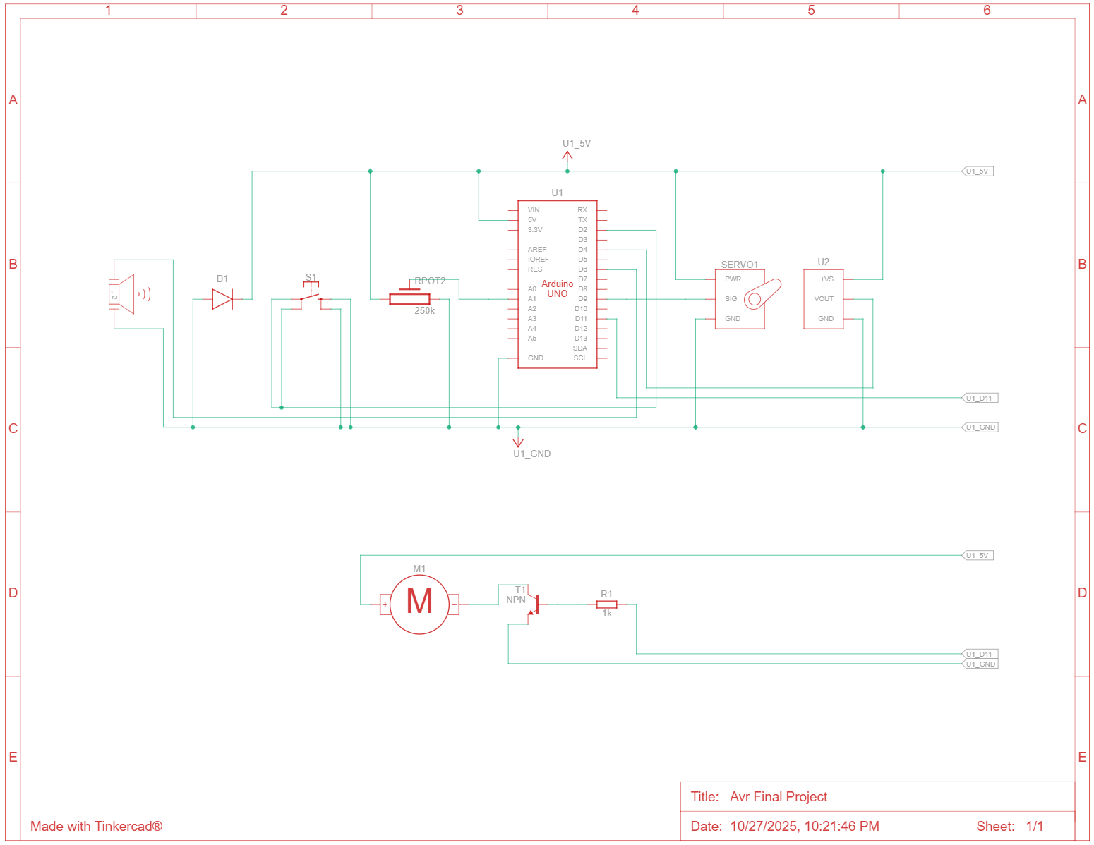
Output behavior includes PWM fan speed control, servo positioning, and buzzer feedback. The fan is controlled through a PWM signal on D11, the servo is connected to D9, the mode button is connected to D2, the buzzer is connected to D6, the DHT11 sensor is connected to D4, and the potentiometer is connected to A1.
The schematic documents the full wiring layout and shows how each input and output connects into the embedded control system.
- ATmega328P used as the main microcontroller
- DHT11 temperature sensor used for environmental input
- PWM signal used to control fan speed
- Potentiometer used as an analog user input
- Servo used for physical movement behavior
- Button input used for mode selection
- Buzzer used for feedback and alert behavior
Testing & Iteration
Testing focused on confirming that each subsystem worked independently and then verifying that the full system behaved correctly when all components were combined. The fan control, temperature sensing, servo movement, button input, potentiometer input, and buzzer output all needed to work together without conflicting.
Rebuilding the code in AVR C also required iterative testing because low-level embedded behavior can be less forgiving than higher-level Arduino code. Pin configuration, timing behavior, PWM setup, and input reading all needed to be checked carefully.
- Verified temperature readings from the DHT11 sensor
- Tested PWM output behavior for fan control
- Confirmed potentiometer input through ADC behavior
- Tested mode switching through the button input
- Checked servo movement and buzzer feedback
- Validated the system using the schematic and demo video
Results & Findings
The Smart Temperature-Controlled Desk Fan successfully demonstrated a complete embedded control system using the ATmega328P. The project combined multiple inputs and outputs into one working platform and showed how a microcontroller can process sensor data, user input, and actuator behavior.
A major result of the project was the successful transition from a basic embedded prototype into an AVR C implementation. This improved the technical depth of the project and made it a stronger example of microcontroller-level programming, hardware control, and embedded design.
The project is a strong portfolio example because it shows both software and hardware integration: the code controls real components, the schematic documents the system, and the demo video shows the behavior in operation.
Future Improvements
Future versions of the Smart Fan could improve the system’s usability, reliability, and appearance by adding more advanced feedback and cleaner hardware packaging.
- Add an OLED or LCD display to show temperature, fan speed, and current mode
- Create a cleaner enclosure for the circuit and fan hardware
- Add stronger power handling for a larger fan motor
- Improve temperature smoothing to reduce sudden fan speed changes
- Add EEPROM memory to save the last selected mode
- Use a more accurate temperature and humidity sensor in a future revision
- Add serial output for debugging and live system monitoring
Technologies Used
Project Links
Demo Video: Watch Smart Fan Demo
GitHub Repository: View Source Code
Demo Evidence: The schematic above documents the full hardware layout, and the linked video demonstrates the programmed smart fan behavior in operation.
Key Contributions
- Rebuilt the project code in AVR C using Microchip Studio
- Mapped and documented the full embedded hardware layout
- Integrated temperature sensing, PWM fan control, servo movement, and buzzer feedback
- Implemented user-controlled mode selection using button input
- Used ADC input from a potentiometer for manual system control
- Tested and documented the system through schematic and demo evidence